Technical Data


■IO-Link
IO-Link is a communication technology for sensors and actuators that is an international standard, IEC 61131-9.
This technology is used to send/receive device information such as manufacturer, product part number, parameters, and diagnostic data, as well as the control data including ON/OFF signals and measured values of the sensor, by connecting the IO-Link master and sensor in a 1:1 configuration.
IO-Link enables condition monitoring and error detection of the sensor and equipment, and it can contribute to the reduction of startup labor and recovery time and the realization of preventive and predictive maintenance.

■IO-Link System Configuration

■Link Interface
The connecting part between the IO-Link master and the device is called a “port.” Each port can be switched between “IO-Link mode” for digital communication and “standard I/O mode” for conventional contact input/output.

There are two methods for power supply: one is for sensors, and the other is for actuators.

■IO-Link Master Unit
・Can be connected with digital, analog, and IO-Link master units
PROFINET: Up to 9 IO-Link master units can be connected. (Total of 36 ports)
EtherNet/IP™: Up to 4 IO-Link master units can be connected. (Total of 16 ports)
Digital units, analog units, and IO-Link master units can be mixed, and up to 9 units can be connected in any order.

・Supports both port class A and port class B

・The data can be accessed from via PC (setting tool).

・Diagnosis function
Diagnosis on a master and device is possible from the upper level communication.
Master (port) diagnostic information can be obtained via PLC program or PC (web browser).
Device diagnostic information can be obtained via PC (setting tool).

・Device parameter setting function, Automatic saving/writing
The parameter setting of devices is possible from the upper level communication.
Parameter setting is possible via PC (setting tool).
It is also possible to use output data or message data via PLC program.

■EtherNet Fieldbus Functions
PROFINET (EX600-SPN3/4) and EtherNet/IP™ (EX600-SEN3/4) support the following functions.
・Compatible topologies (Connection configuration)

・Supports the QuickConnect™ function and the Fast Start Up function

・Built-in web server function
The EX600-SEN3/4 and EX600-SPN3/4 have a built-in web server function, which enables status checks, parameter settings (EX600-SEN3/4 only), and forced output of the EX600 using general-purpose web browsers, such as Microsoft Edge.
Start-up of the system and maintenance can be performed efficiently.

■Latest PROFINET Technology
System Redundancy S2
As the EX600-SPN3/4 supports System Redundancy S2, it can continue communication using the backup controller when the primary controller malfunctions. This allows for the prevention of problems caused by unexpected communication interruption.
* In order to use System Redundancy S2, the PLC must be able to support this function.

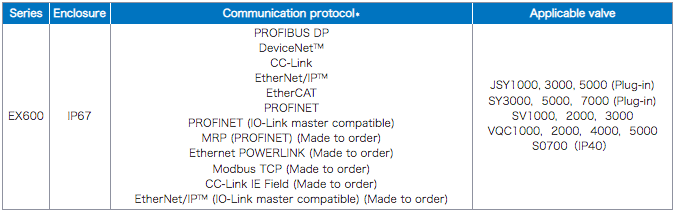
■Fieldbus System EX600