Technical Data


■Supports “System Redundancy S2” New
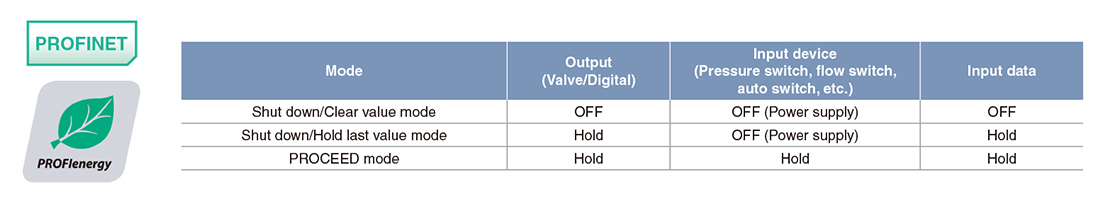
■Compatible with the PROFIenergy energy-saving function
Generally, after factory facilities are shut down, it takes a lot of time to restart them.
PROFIenergy enables PROFINET communication to continue while saving energy by minimizing restart times. When the commands for PROFIenergy energy-saving mode are sent from the I/O controller (PLC) to the I/O device (SI unit), information regarding downtimes is also sent (such as lunch breaks, nighttime, weekends, and holidays).
SMC SI units do not require time for restarting. However, for the connected I/O equipment, such as pressure switches, flow switches, auto switches, and valves, 3 types of energy-saving modes are available for customers to choose from depending on the application.
■Shared Device function
An I/O module connected to an SI unit can be controlled by multiple I/O controllers (PLC).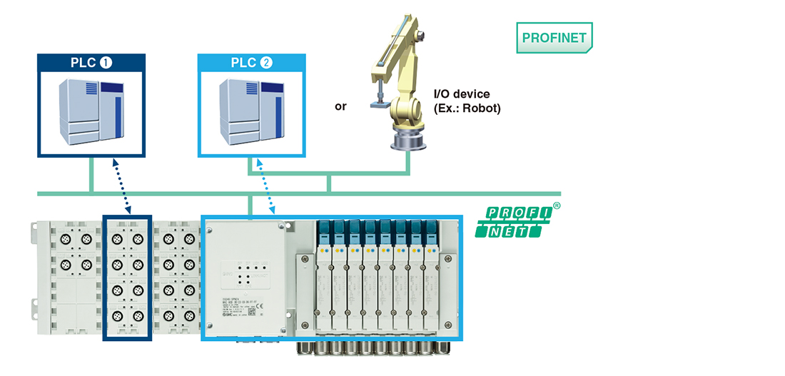
・Information can be shared with up to 3 controllers in addition to the control PLC.
・The cost of the hardware, cables, and installation space can be reduced.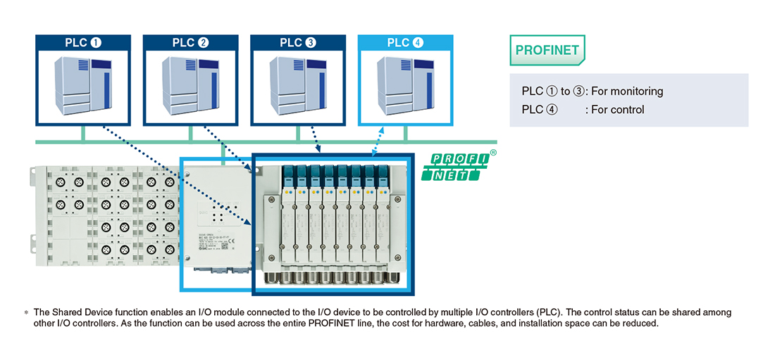
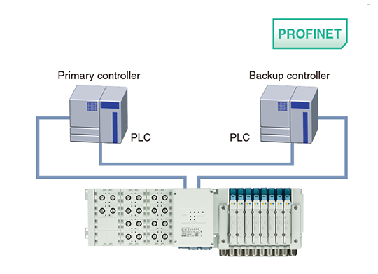
■System Redundancy S2 function New
As the EX245-SPN1/2/3A supports System Redundancy S2, it can continue communication using the backup controller when the primary controller malfunctions.
This allows for the prevention of problems caused by unexpected communication interruption.
∗ In order to use System Redundancy S2, the PLC must be able to support this function.
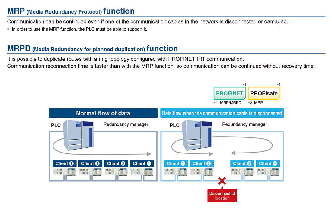
■MRP/MRPD function
■NET Load Class Ⅲ compatible [PROFINET]
Passed and certified under the highest network load (Class Ⅲ) specified by PROFINET
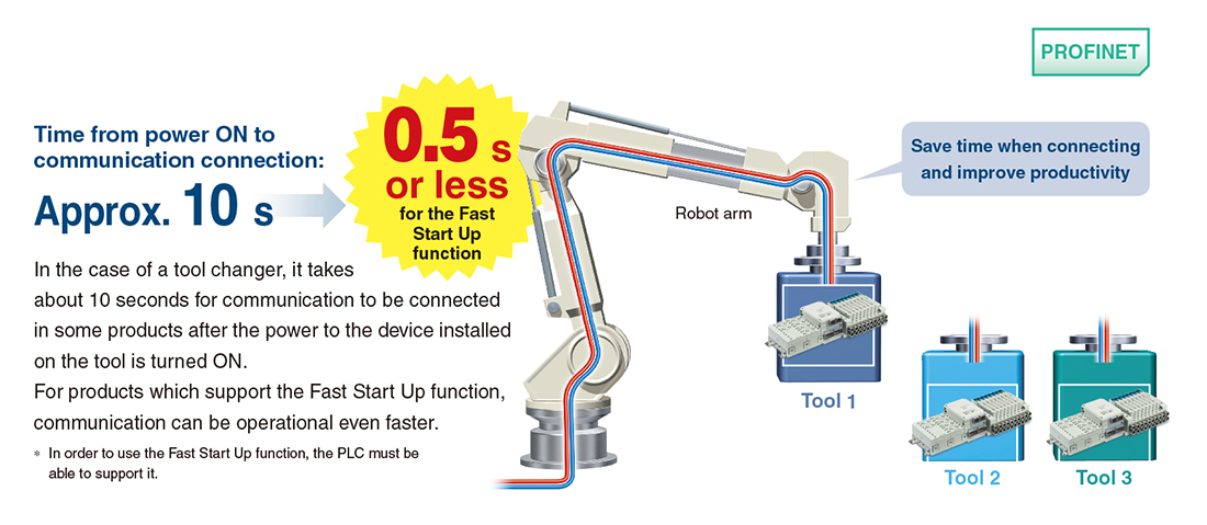
■Fast Start Up function
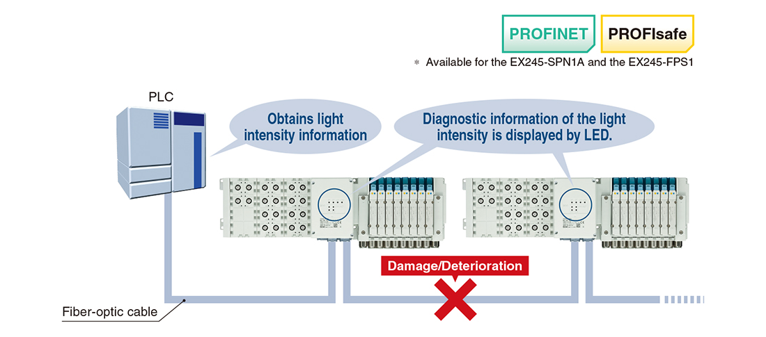
■Fiber-optic cable maintenance alarm
This feature continuously monitors the received light intensity from the fiber-optic cable and reports it to the PLC. Any loss of intensity is an indicator of damage to the cable, so may give a warning before communication is lost.
By using preventative maintenance, you can avoid unexpected shutdowns.
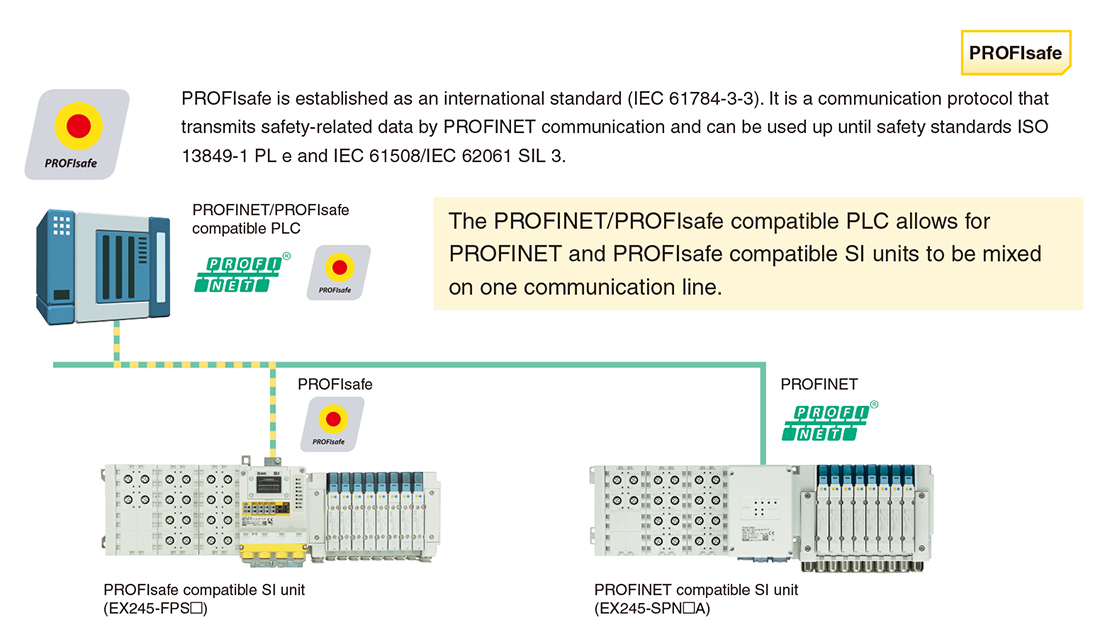
■Supports safety communication (PROFIsafe)
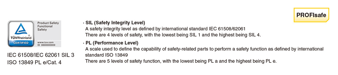
■Compliant with safety standards
The aim is to facilitate a safe design (featuring ISO/IEC compliance) of the customer’s equipment and facilities. The EX245-FPS□ has been certified under the following categories by a third-party organization (TÜV Rheinland).
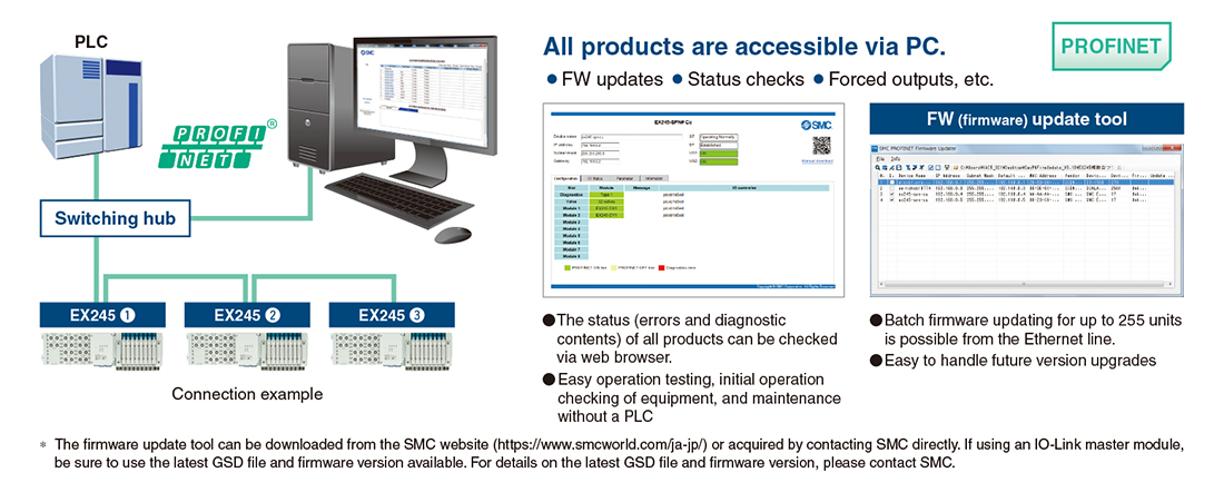
■Built-in web server function, FW (firmware) updates
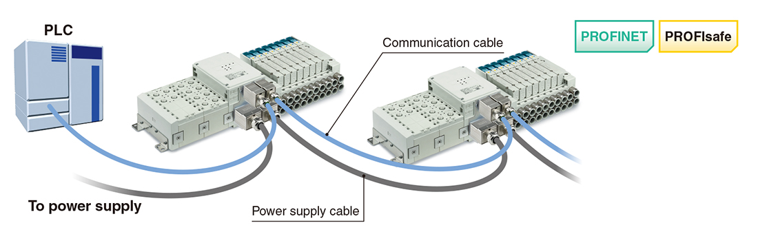
■Dual communication and dual power connectors
・2 power connectors and 2 communication connectors are mounted, making daisy-chain connection possible. ・An external branch connector is not necessary. Reduced wiring space
・Loop through current between power connectors: Max. 16 A*
* The max. allowable current for the 7/8 inch power supply connector is 10 A. The max. loop through current between connectors is 6 A.
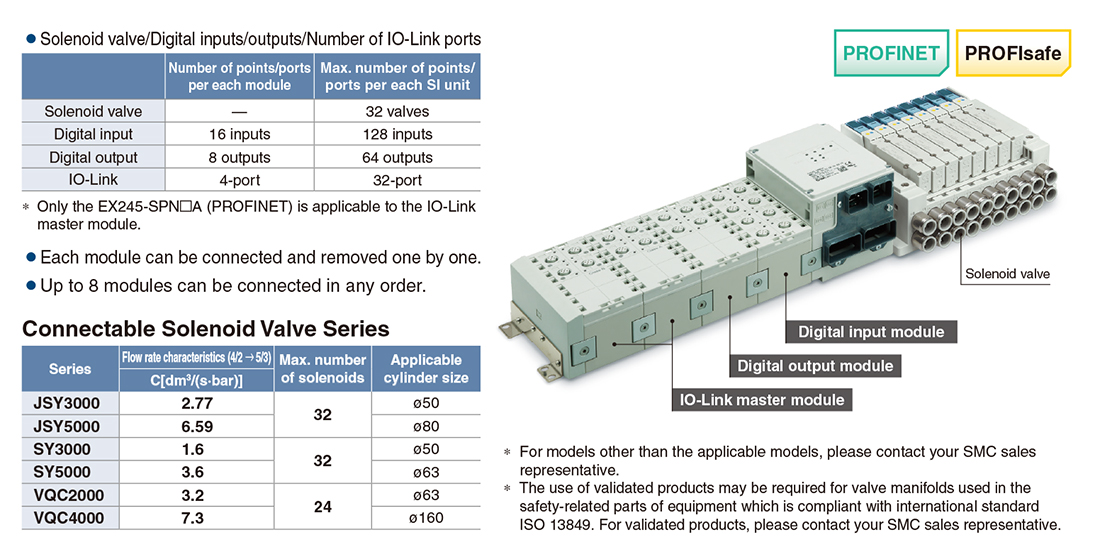
■Modules can be combined flexibly.
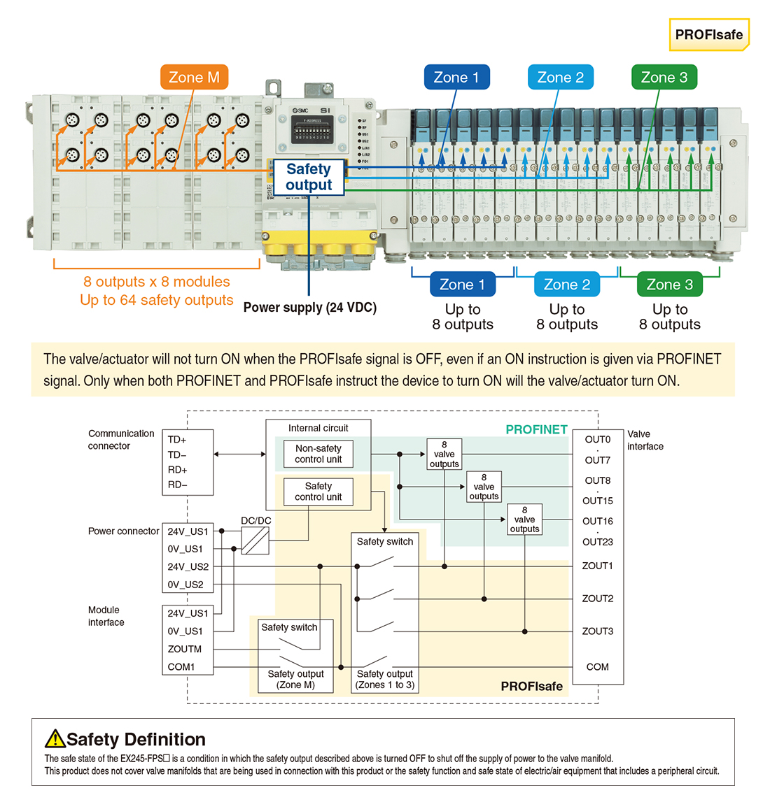
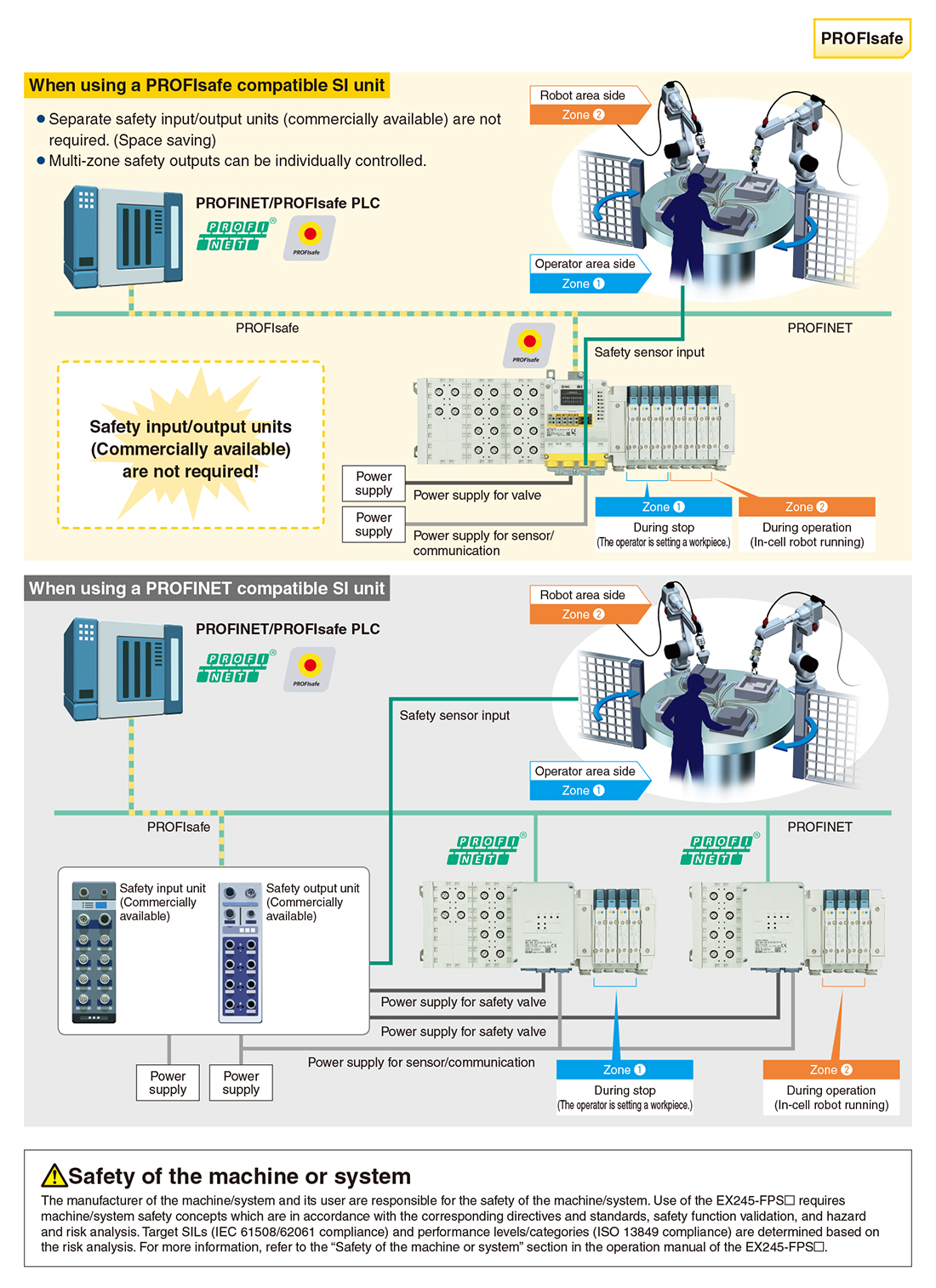
■Safety Output
The EX245-FPS□ has safety outputs inside the product that can control 3 zones for valves and 1 zone for output modules individually. When the safety switch is turned OFF by directive from the PLC, the voltage supplied to the valve or output module is shut off, and it switches to safe state.
The safety switch of this product has two redundancies, one on the 24 V side and the other on the 0 V side. It continuously runs diagnostics.
The safety switch is turned OFF in the event of an error detection.
■Safety Input
The EX245-FPS□ is equipped with safety inputs. The safety inputs of this product can connect to components (e.g. laser scanners, light curtains, etc.) that are compatible with the safety inputs.
The safety input can be loaded in 2 ways:
・Single channel (1 out of 1): 8 safety inputs (SIL 2/PL d)
・Dual channel (1 out of 2): 4 safety inputs (SIL 3/PL e)
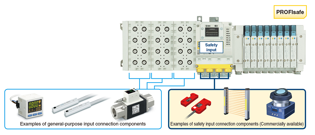
■Safety Input/Output Construction Example
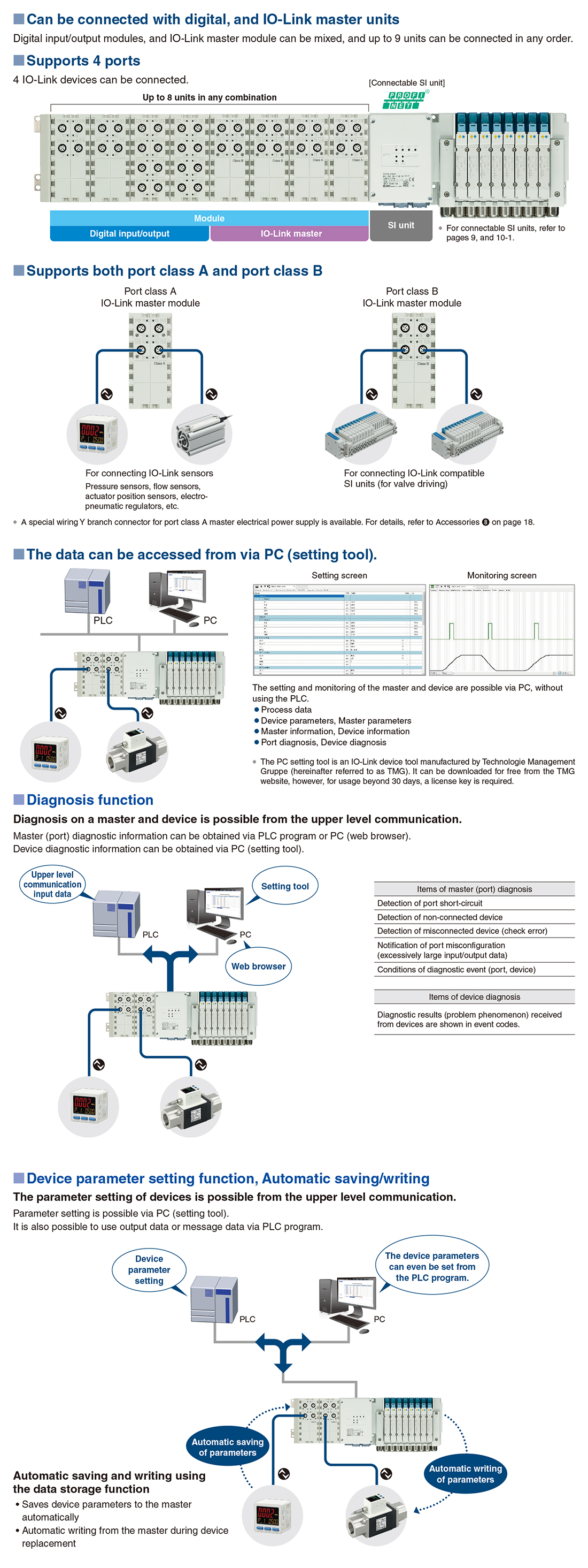
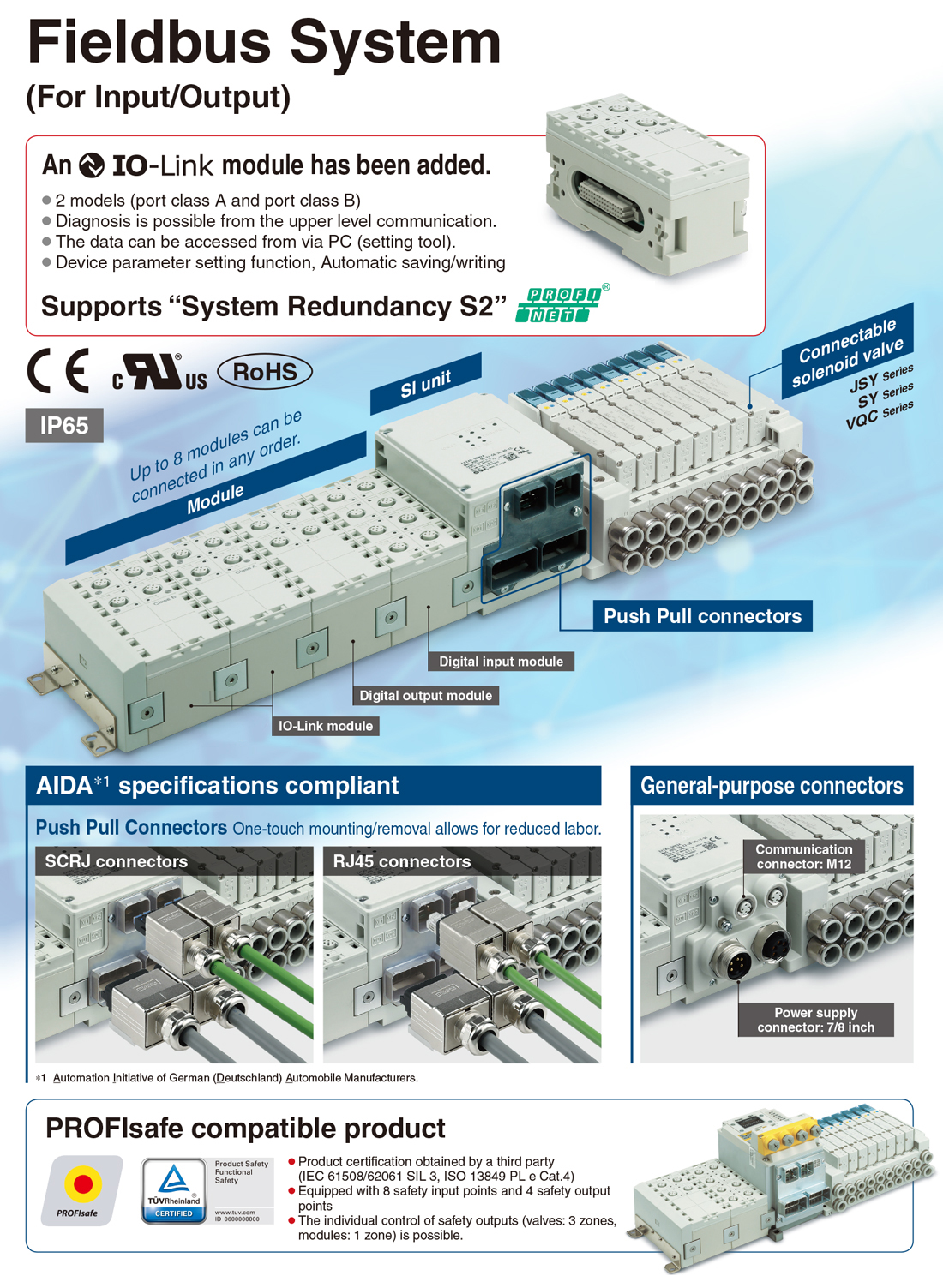
■IO-Link
IO-Link is a communication technology for sensors and actuators that is an international standard, IEC 61131-9.
This technology is used to send/receive device information such as manufacturer, product part number, parameters, and diagnostic data, as well as the control data including ON/OFF signals and measured values of the sensor, by connecting the IO-Link master and sensor in a 1:1 configuration.
IO-Link enables condition monitoring and error detection of the sensor and equipment, and it can contribute to the reduction of startup labor and recovery time and the realization of preventive and predictive maintenance.
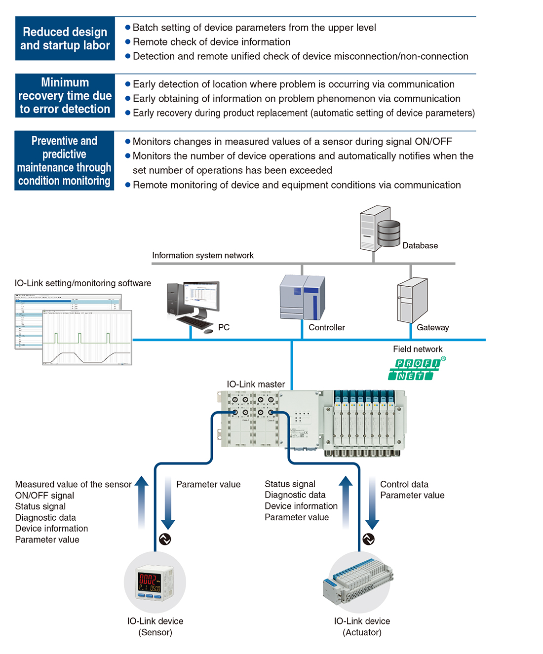
■IO-Link System Configuration
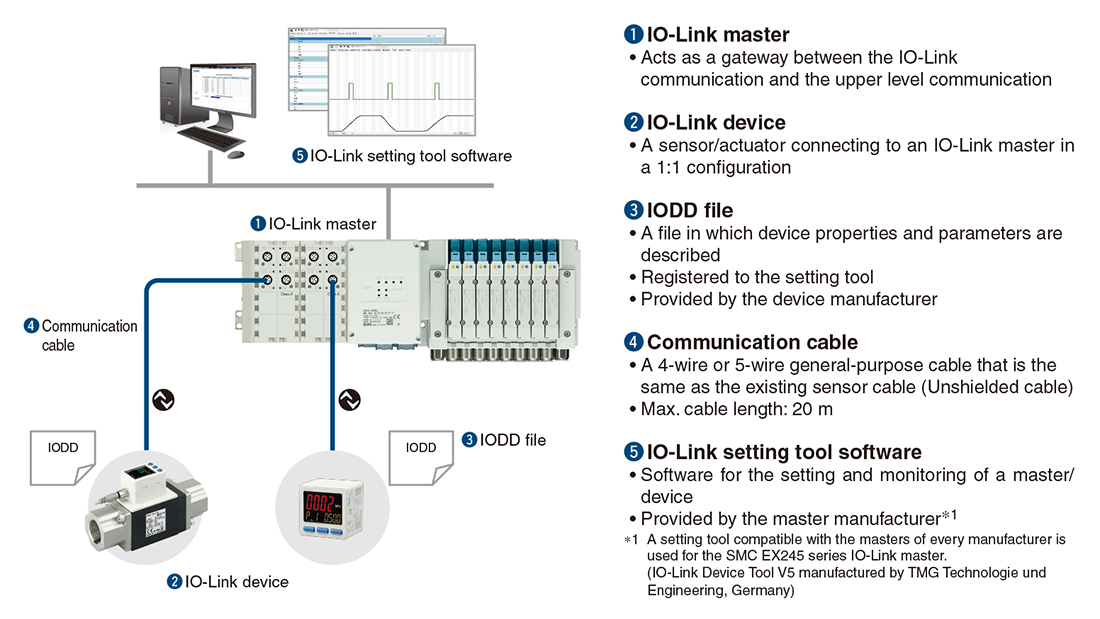
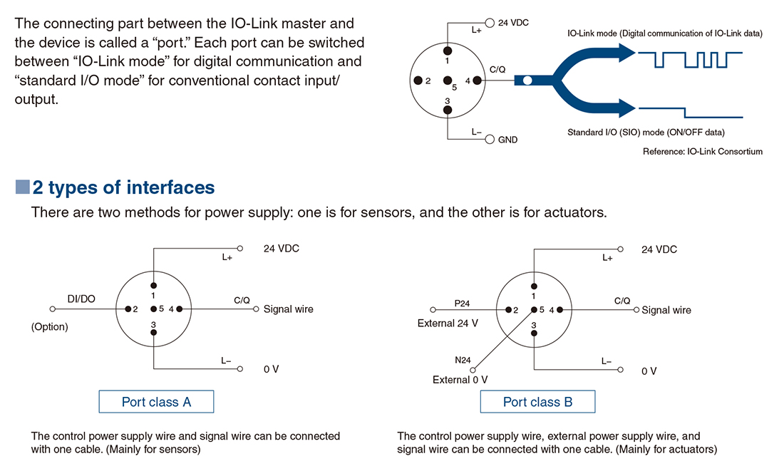
■IO-Link Interface
■IO-Link Master Module [PROFINET]